
When engineers compare a current transformer vs potential transformer, they are looking at two members of the same family: instrument transformers. Both make high-voltage, high-current systems safe to measure. Both feed meters and protection relays. However, they work in very different ways, connect differently and carry different safety risks.
So this guide explains what each device does, how it works and where it is used. It also covers selection, accuracy classes, burden and the safety rules every maintenance team should know.
Key Takeaways
- A current transformer (CT) steps a large current down to a small standard value, usually 1 A or 5 A, and connects in series with the circuit.
- A potential transformer (PT), also called a voltage transformer (VT), steps a high voltage down to a standard value, such as 100 V, 110 V or 120 V, and connects in parallel.
- Metering transformers prioritise accuracy under normal conditions; protection transformers must stay reliable during faults.
- A CT secondary must never be left open-circuited while the primary is energised, because dangerous voltages can develop.
- Similarly, a PT/VT secondary must never be short-circuited, so it is normally protected with fuses or circuit breakers.
Table of Contents
Why Instrument Transformers Are Used
Before looking at the current transformer vs potential transformer differences, it helps to know why these devices exist. After all, meters and relays cannot connect directly to a 13.8 kV feeder or a busbar carrying thousands of amps. Instrument transformers therefore solve that problem in three ways:
- Scaling: they reduce current and voltage to standard levels that instruments can handle.
- Isolation: they also separate the measuring circuit from the high-voltage system, which protects people and equipment.
- Standardisation: finally, they allow one type of meter or relay to work across many system sizes.
Requirements for these devices are covered by the IEC 61869 series, including IEC 61869-2 for current transformers and IEC 61869-3 for inductive voltage transformers. Meanwhile, in North American practice, IEEE C57.13 sets requirements for instrument transformers.
What Is a Current Transformer (CT)?
A current transformer produces a secondary current that is proportional to the current in its primary conductor. It is rated by ratio, for example 400/5 A or 1000/1 A. So a 1000/5 A CT delivers 5 A on its secondary when 1,000 A flows in the primary.
The primary is often just the main conductor or busbar passing through the CT’s core. In contrast, the secondary has many turns, which is what reduces the current. For a deeper look at CT types and features, read our guide on how current transformers keep electrical systems safe in Saudi Arabia.
What Is a Potential Transformer (PT)?
A potential transformer, more commonly called a voltage transformer (VT) in IEC terminology, reduces a high system voltage to a low, proportional value. For example, an 11,000/110 V VT delivers 110 V on its secondary when the primary sees 11 kV.
Its primary connects across the line, either phase-to-phase or phase-to-earth. Its secondary then feeds voltmeters, energy meters and protection relays. At very high transmission voltages, capacitor voltage transformers (CVTs) are also common.
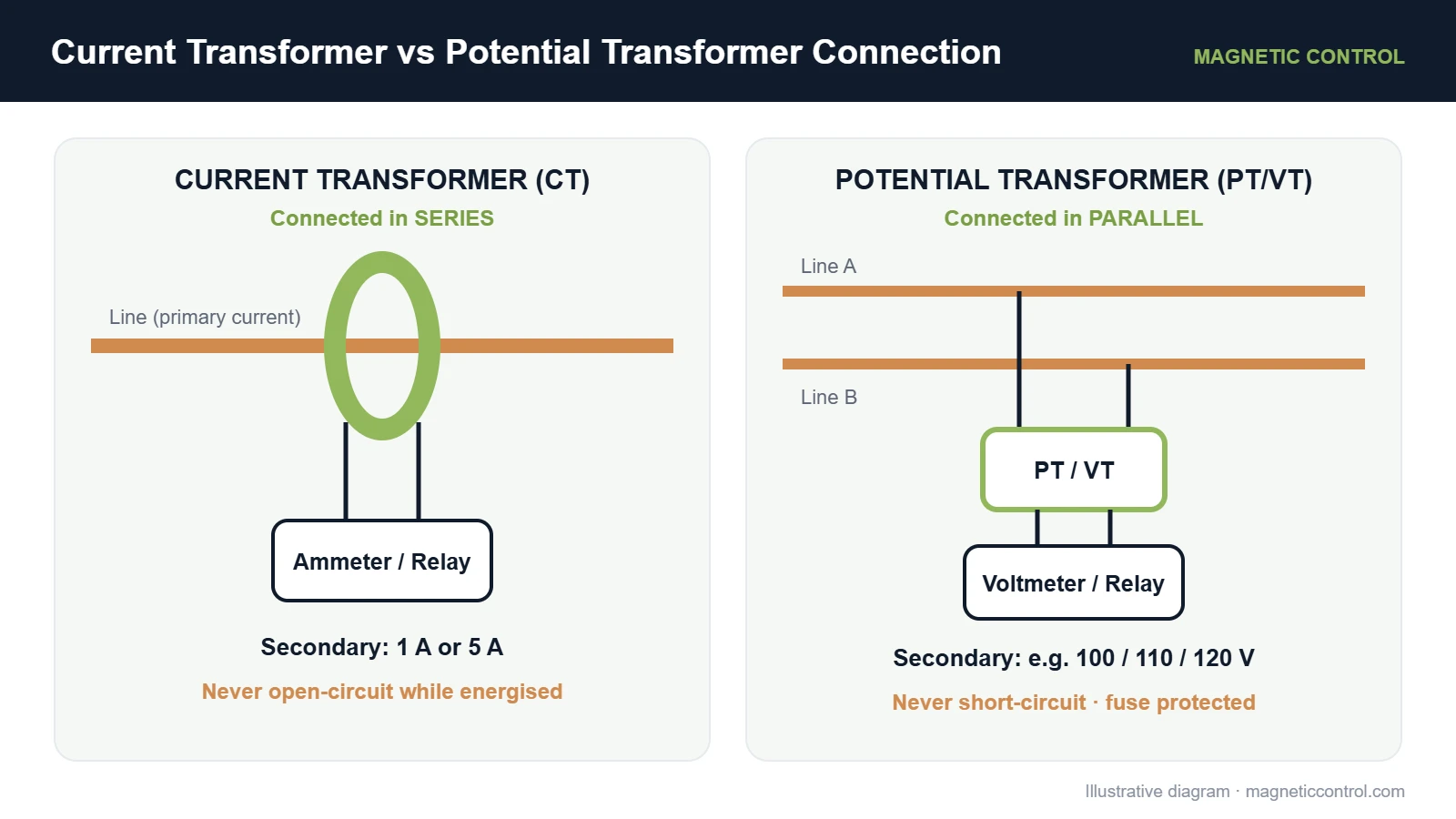
How a Current Transformer and Potential Transformer Work
How a Current Transformer Works
Current in the primary conductor creates a magnetic flux in the CT core. Then this flux induces a current in the secondary winding. The secondary current is roughly the primary current divided by the turns ratio. Because the secondary burden is very small, the CT operates close to a short-circuit condition. That is normal and expected.
How a Potential Transformer Works
This is where the current transformer vs potential transformer contrast becomes clear. A PT works like a small, very accurate step-down power transformer. Here, the primary voltage drives flux through the core, and the secondary winding produces a proportional lower voltage. The connected burden draws only a small current, so the PT operates close to an open-circuit condition.
Engineering Insight — Instrument Transformers
“A CT is designed around a controlled current, while a PT is designed around a controlled voltage. Treat their secondary circuits accordingly: keep CT secondaries closed and keep PT secondaries protected against short circuits.”
Original editorial insight from the Magnetic Control content team.
Current Transformer vs Potential Transformer: Comparison Table
The table below sums up the current transformer vs potential transformer differences at a glance.
| Feature | Current Transformer (CT) | Potential Transformer (PT/VT) |
|---|---|---|
| Measures | Current | Voltage |
| Connection | In series with the line | In parallel across the line |
| Typical secondary rating | 1 A or 5 A | Commonly 100 V, 110 V or 120 V (system dependent) |
| Primary winding | Few turns, often a single conductor | Many turns |
| Secondary winding | Many turns | Fewer turns |
| Normal operating condition | Close to short circuit | Close to open circuit |
| Primary quantity depends on | The load current in the system | The system voltage |
| Main secondary hazard | Open circuit while energised | Short circuit |
| Secondary protection | Shorting links/terminals for safe isolation | Fuses or miniature circuit breakers |
| Ratio example | 1000/5 A | 11,000/110 V |
Difference Between CT and PT in Applications
The key difference between CT and PT in daily use is what they feed. For example, CTs supply current inputs to ammeters, energy meters and overcurrent, differential and earth-fault relays. PTs supply voltage inputs to voltmeters, energy meters, synchroscopes and voltage-based relays such as under-voltage, over-voltage and distance protection.
Many devices need both. An energy meter, for example, multiplies current from CTs with voltage from PTs to calculate power and energy. Similarly, directional and distance relays need both inputs to locate faults.
Current Transformer vs Potential Transformer in Protection and Metering
Instrument transformers are designed for one of two broad duties, and they are not always interchangeable.
- Metering duty: high accuracy within the normal operating range. For billing, especially, small errors add up over time.
- Protection duty: reliable performance during faults, when currents may be many times higher than normal. A protection CT must not saturate before the relay can act.
A metering CT may saturate during a fault, which actually helps protect the connected meter. A protection CT, by contrast, is built to reproduce fault currents faithfully. In addition, some CTs have multiple cores to serve both duties from one unit.
Current Transformer vs Potential Transformer Accuracy Classes and Burden
Burden is the load connected to the secondary, including meters, relays and the connecting wiring. It is usually expressed in VA. So if the actual burden exceeds the rated burden, accuracy can suffer.
Accuracy class defines the permitted error. Under IEC 61869, typical examples include:
- Metering CTs: classes such as 0.1, 0.2, 0.2S, 0.5, 0.5S and 1.
- Protection CTs: classes such as 5P and 10P, often with an accuracy limit factor, for example 5P20. Special classes such as PX are used for certain schemes.
- Metering VTs: classes such as 0.2, 0.5 and 1.
- Protection VTs: classes such as 3P and 6P.
Therefore, always confirm the exact class required by the relay, meter or utility specification for your project.
Current Transformer and Potential Transformer Selection
Once you understand the current transformer vs potential transformer roles, selection becomes a matter of matching each device to its duty. Check these points:
- System voltage and insulation level: match the device to the system it will connect to.
- Ratio: choose a CT primary rating suited to the expected load and fault currents, and a PT ratio that matches system voltage.
- Accuracy class: metering, protection or both.
- Rated burden: include all loads, such as meters, relays and cable losses.
- Short-time and thermal ratings: the CT must withstand fault currents for the required duration.
- Installation type: for example, indoor or outdoor, window, bar or wound type, and the available space.
- Environmental conditions: in Saudi Arabia, consider high temperatures, dust and enclosure ratings.
- Applicable specifications: utility, consultant or owner requirements may set specific ratios or classes.
Current Transformer and Potential Transformer Safety
Critical safety warning: Never open-circuit the secondary of an energised current transformer. That is because, with no secondary current to oppose it, the core flux can rise sharply and produce dangerous voltages across the open terminals, which can harm people and damage the CT. Work on CT secondary circuits must follow approved procedures and the manufacturer’s instructions, typically using shorting terminals before any device is disconnected.
Similarly, PT and VT circuits need equal respect. For example, a short circuit on a PT secondary can cause very high current and damage the transformer. So PT secondaries are normally protected with fuses or circuit breakers, and they must be isolated according to approved procedures before work begins.
Other good practices include:
- Earth the secondary circuits of CTs and PTs as specified by the design and applicable standards.
- Check polarity markings carefully, since reversed connections affect directional relays and power meters.
- Keep secondary wiring short and correctly sized so that burden stays within limits.
- Allow only qualified and authorised personnel to work on instrument transformer circuits.
Common Current Transformer and Potential Transformer Mistakes
- “Any CT will do for protection.” Not true. A metering CT can saturate during faults and prevent a relay from operating correctly.
- “PT and VT are different devices.” They are the same thing. PT is the older or regional term, whereas VT is the IEC term.
- Ignoring burden: long cable runs and extra devices can push burden beyond the rating.
- Wrong ratio: similarly, an oversized CT ratio reduces accuracy at low load currents.
- Unsafe isolation: disconnecting a meter from a live CT circuit without first shorting the secondary.
Practical Applications in Industrial Electrical Systems
In Saudi industrial plants, commercial buildings and utility networks, CTs and PTs appear in many places:
- Main incoming switchgear for revenue metering and protection.
- Motor control centres for overload and earth-fault protection.
- Generator panels for synchronising and protection.
- Transformer protection schemes, such as differential protection.
- Power quality monitoring, alongside equipment such as harmonic filters.
Of course, instrument transformers work alongside power and distribution transformers in the same system. If you are sizing the main transformer as well, our guide on how to calculate transformer kVA can help, and you can explore Magnetic’s transformer product range.
When to Consult a Qualified Electrical Engineer
Speak with a qualified engineer when you are specifying CTs or PTs for protection schemes, revenue metering, high fault-level systems or utility connections. For example, an engineer can check ratios, accuracy classes, burden, saturation performance and compliance with the project specification. They can also confirm safe isolation procedures for maintenance teams.
Looking for the Right Transformer Solution for Your Electrical System?
So discuss your electrical system requirements with Magnetic Control and identify the appropriate equipment for your metering, protection or power distribution application.
Frequently Asked Questions
What is the main difference between a current transformer and a potential transformer?
A current transformer measures current and connects in series with the circuit. In contrast, a potential transformer measures voltage and connects in parallel across the circuit. However, both scale system values down to standard levels for meters and relays.
Is a potential transformer the same as a voltage transformer?
Yes. Potential transformer (PT) and voltage transformer (VT) refer to the same device. VT is the term used in IEC standards, while PT is still common in many regions.
Why should a CT secondary never be open-circuited?
If the secondary of an energised CT is opened, there is no secondary current to balance the primary. As a result, the core flux can rise sharply and produce dangerous voltages across the terminals. Always follow approved procedures, such as using shorting terminals, before disconnecting a device.
Can a metering CT be used for protection?
Generally, no. Metering CTs are accurate under normal conditions but may saturate during faults. Therefore, protection relays need protection-class CTs that reproduce fault currents reliably.
What are typical secondary ratings for CTs and PTs?
CT secondaries are usually rated 1 A or 5 A. Meanwhile, PT secondaries are commonly 100 V, 110 V or 120 V, depending on the system and applicable standards. Always confirm with the project specification.
Conclusion
The current transformer vs potential transformer comparison comes down to what each device measures and how it connects. CTs connect in series and scale current, while PTs connect in parallel and scale voltage. In addition, both need correct selection for accuracy, burden and duty, and both demand careful safety practice on their secondary circuits. When you plan metering, protection or power distribution for a project in Saudi Arabia, talk to Magnetic’s team about the right equipment for your system.